TagThird Runway(1084)
-
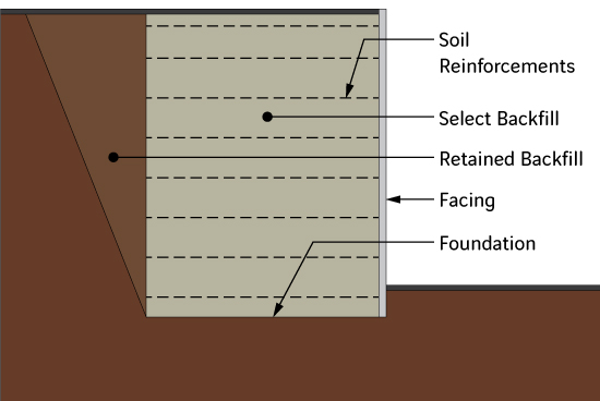
Diagram_MSE
Technical cross-section diagram illustrating the components of a Mechanically Stabilized Earth retaining wall, including labeled elements: soil reinforcements, select backfill, retained backfill, facing, and foundation. This type of structure is commonly used in transportation and geotechnical engineering applications. -
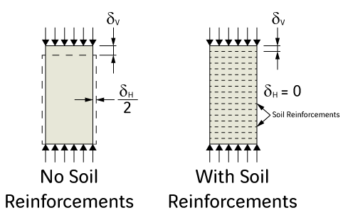
MSE_graphic
A structural/geotechnical engineering diagram comparing horizontal and vertical displacement behavior of a soil block with and without soil reinforcements. The left panel shows lateral displacement (δH/2) occurring without reinforcements, while the right panel shows zero lateral displacement (δH=0) when soil reinforcements are present, with only vertical settlement (δV) in both cases. -
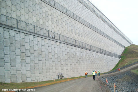
seaTac2
A massive segmental concrete block retaining wall is shown under construction, with workers in high-visibility safety vests visible at its base for scale. A watermark reading 'Photo courtesy of Hart Crowder' is visible in the lower left corner. -
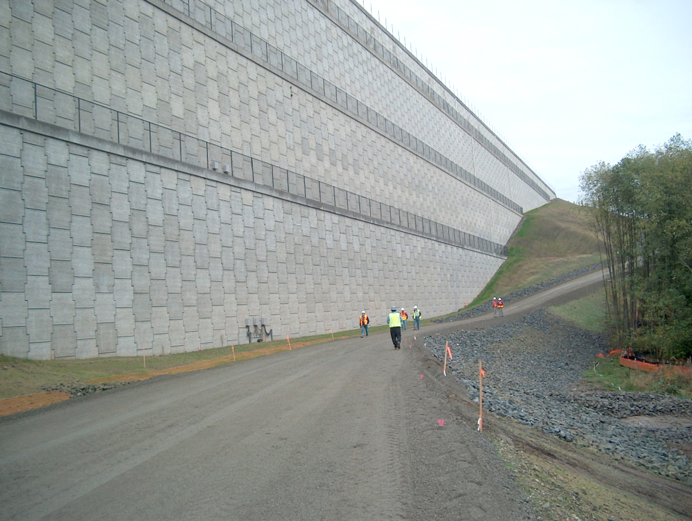
Third Runway Retaining Wall
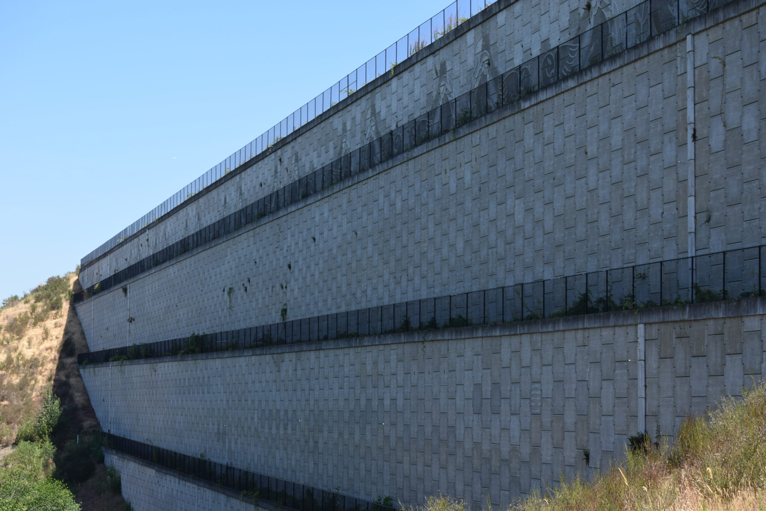
Construction workers in high-visibility vests and hard hats walk along the base of a massive segmental concrete block retaining wall, several stories tall. The site shows a gravel access road and erosion control markers, consistent with an active earthwork or infrastructure project. -
-
seaTac3
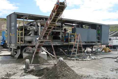
A large mobile industrial processing or water treatment unit is shown at an active work site, with visible mud, hoses, ladders, and heavy machinery. A watermark in the lower left reads 'Photo courtesy of Clear Water Compliance.' -
-
Design and Performance of a 46-m-High MSE wall-edge
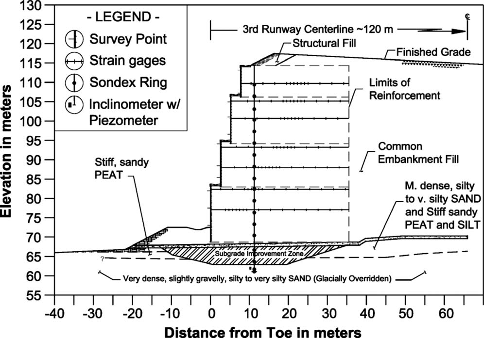
Geotechnical cross-section diagram of the Sea-Tac Airport Third Runway embankment, showing soil layers including stiff sandy peat, glacially overridden sand, and a subgrade improvement zone. The diagram details instrumentation locations (strain gages, Sondex rings, inclinometers with piezometers) and structural elements including reinforced fill limits and common embankment fill, with the runway centerline approximately 120 meters from the embankment toe. -
 2022-09-12
RCAA scoping comments on the “Sea Tac Master Plan Update, including a third runway”
The Regional Commission on Airport Affairs (RCAA) submitted formal scoping comments on the proposed Sea-Tac Airport Master Plan Update, which includes the addition of a third runway, calling for the Environmental Impact Statement to comply fully with both federal NEPA and state SEPA requirements. The RCAA emphasized that the EIS must be a comprehensive, nonpartisan document that is accessible to ordinary citizens and public officials, complete with proper citations, consistent terminology, indexed appendices, and clearly sourced maps and data. The comments also urged that all environmental impacts be analyzed across multiple time horizons, including the full useful life of the proposed runway, and that all study documents be made freely available to the public throughout King and Pierce Counties. -
 2022-09-12
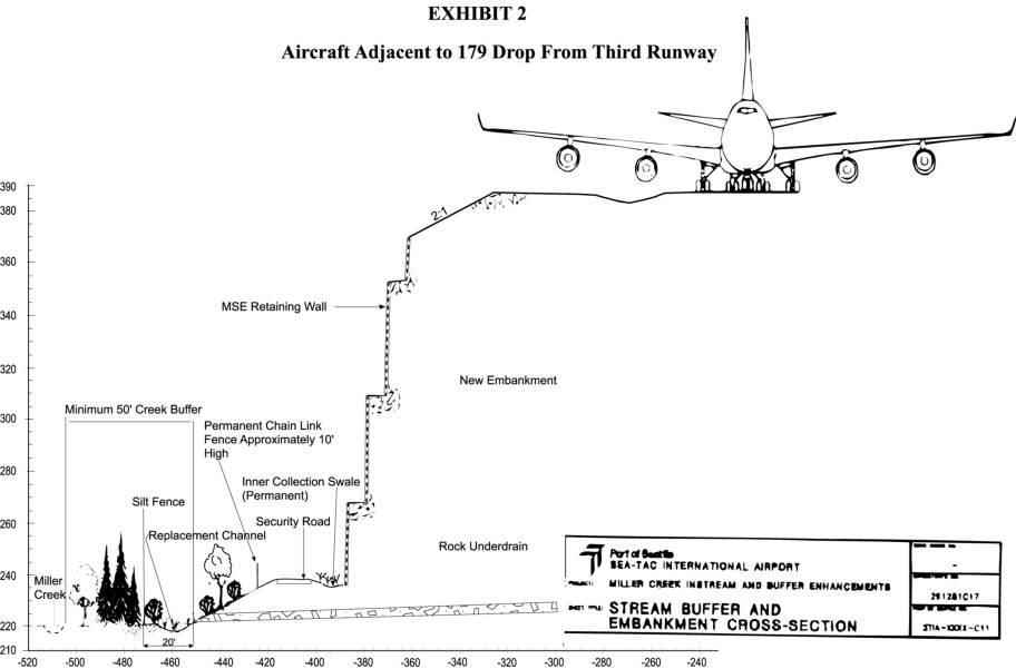
Aircraft adjacent to 179 drop from third runway
This engineering cross-section diagram from Sea-Tac International Airport illustrates the dramatic 179-foot elevation drop adjacent to the proposed Third Runway, showing how a massive retaining wall and new embankment would be constructed alongside Miller Creek. The exhibit depicts key infrastructure features including a permanent chain-link security fence, rock underdrain, silt fence, inner collection swale, and a minimum 50-foot creek buffer zone designed to protect the existing waterway. The drawing is part of the Miller Creek Instream and Buffer Enhancements project documentation associated with the Third Runway expansion.